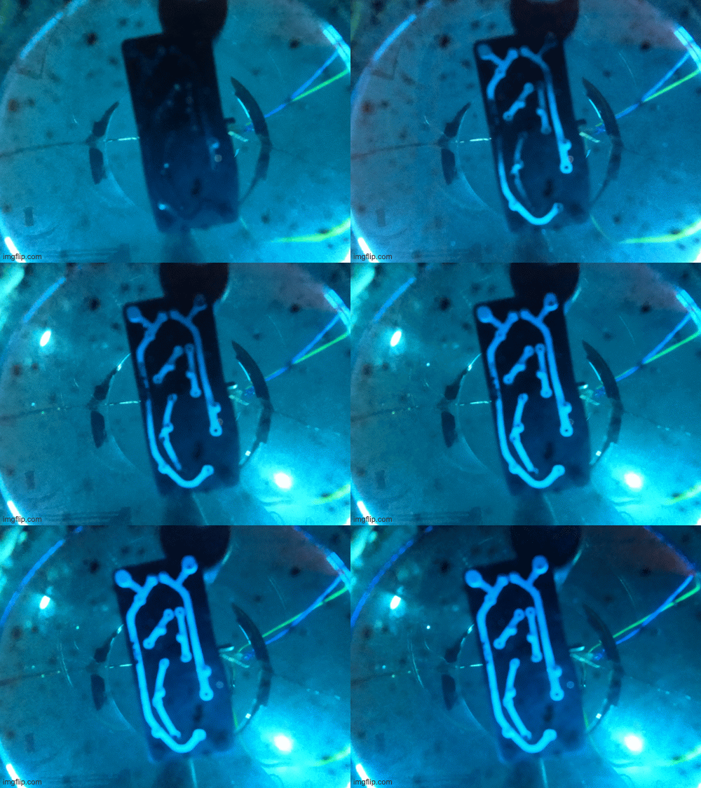
Tl;dr
ProjectQuine is working on self-replicating machines. We are currently exploring 3D printing motors and electronics. Using conductive filament and electroplating, we can produce functional PCB’s. Next up are motor coils!! If you want to follow the series and as we build subscribe to our substack.
Intro
After messing around with various chemicals, copper and plastic for the last 2 months or so, it’s time to write some of this down. This is the inaugural ProjectQuine post in a series detailing our exploration into self-replicating machines.
Over a year ago Alexandros (@alexandrosM) started worrying about the world’s logistics systems and figured we need localised and self-sufficient production. There is a detailed twitter thread on the thinking below, but the crux is we need self-replicating robots.

Starting from the base of a FDM 3D printer, one of the first major hurdles you bump up against is the motion system. How the hell do we print a motor?! There are various interesting builds of PCB based steppers and BLDC motors. That coupled with the discovery of being able to electroplate conductive 3D print filament (current conductive filaments are not conductive enough to make anything useful), gives us the primitives to start making 3D printed circuit boards and eventually motors!
Enough Waffle, tell me how?!
At a high level the idea was simple.
Print something multi-material using conductive filament
Whack it in an electroplating setup for a few hours
Profit??
…Unfortunately, reality is way less kind and we went through a ton of iterations and failures. Often times electroplating felt like a dark art rather than a science. Our test for all of this was a simple single transistor flashing LED circuit and you can download the printable model here.
Initially we started with a distilled white vinegar and Copper sulphate pentahydrate solution. This solution sort of worked but we were constantly unable to plate the full length of the traces and copper would just build up thick near the points of connection. The copper deposition was generally pretty lumpy and rough as well. We could only get a fully plated print by strategically moving the electroplating clips to different parts of the print and letting it plate for a while. However, that kinda song and dance is not super automatable (is that a word?), so we needed something better.
In the plating world there is a concept known as “Throwing Power” which is a measure of a solution's ability to plate to a uniform thickness over the entirety of an irregularly shaped object [1]. It turns out that our homemade brew has pretty weak throwing power, I think because vinegar is only at best 5% acidic. This is why most industrial electroplating processes use a sulphuric acid or cyanide solution. Since we are doing this from a home office, we definitely didn’t want to mess around with cyanide, so sulphuric acid was the next stop. Here, one can either make your own following a recipe like this “Acid Copper Plating solution”, or you can buy a ready made solution. In Europe you can pick it up from DrGalva.com or Tifoo for around €20.
The sulphuric acid based solution made a dramatic difference and we started getting much smoother and longer plates. It was quicker as well! You can see a comparison below. The vinegar based solution produced that very rough finish seen on the right.
With the new solution we were much closer to a reproducible print and plate procedure. However, we were still failing on the regular. It seems that our idea of extending columns out of the circuit traces as a mechanism to connect the plating clips lead to a pretty uneven plating and quite often one of the traces would plate super fast and then continue to just sip up all the copper leaving the other traces bare. You can see an example of that type of failure here where the bottom most trace has tons of copper built up and the rest are barely plated:
One of the ideas we had thrown around a bit was whether it would be possible to plate components in place and negate the need to solder components at all (more on soldering later). This idea was the basis for our “plating rivets”. We found that if we placed 0.1” header pins in the through holes, and faced the circuit down in solution with jumper jerky wires connected to each pin, we would get a much more consistent plate. On top of this the pins would actually plate into the trace and create a sort of “rivet”!
Now obviously it’s not super useful to have a circuit with a bunch of pins and no holes for components. So we adapted the model and added a number of through-holes at strategic points on each of the traces. Through testing we found that a single pin can plate about 40 mm of trace, assuming traces of 1mm width and 0.5mm tall. In addition, having the metallic pins appear to allow the current to flow better In our previous approach where we connected a number of crocodile clips to the printed columns that protruded from the traces, our PSU would barely register any current flow, a high voltage would barely register even 1 or 2 milliamps on the dial. However with the pins in place, we get a much more consistent current flow, even at 0.2 Vdc.
With this new found technique, we do need to be a lot more careful with our max current. For this reason it’s necessary to use a PSU capable of current control. To plate our test circuit, we needed to limit the current to 30mA. We found that generally, the best plating was about 0.15 mA/mm2, but we need to still do some more rigorous experimentation to get that dialed in. We have started documenting the setup and process over on the ProjectQuine github, so check it out if you are interested in trying this yourself.
Lets make something actually useful
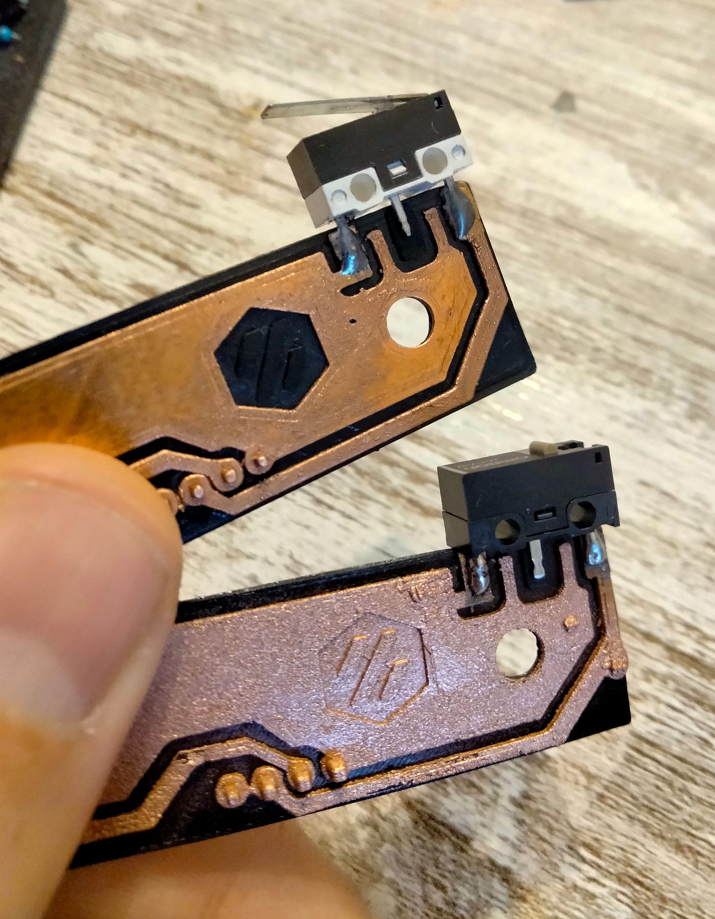
Not content with simple flashing lights, we wanted to produce an actual part for a 3D printer. So we started simple with this microswitch endstop PCB for the XY gantry of Voron 2.4.
It’s a super simple circuit but has a very large ground plane and its design files are fully open source on github, so it was an ideal test candidate. We printed and plated a number of these and with the new plating rivet method we got some really great plating. I absolutely love how the Voron logo inlay looks in plated copper 😍 .
Both of these are completely functional PCBs, even if the soldering is a bit janky. There is still a lot to work out with this process, for instance, we aren’t sure why the bottom one has a rougher and more salmon finish. Peculiarities aside, these two test circuits prove out the basic approach fairly well and we can move onto more complex things while continually refining the process.
Problems to solve
While we have things working fairly well, there are still a few limitations and details to improve. For one, soldering plastic is fairly difficult. One needs to move pretty quickly to prevent the PLA from melting. There is some room to explore with low temperature solder and reflow ovens. Perhaps, simultaneously soldering and annealing the whole print 🤣
The plating process is fairly slow. Currently it takes 9 or 10 hours to plate a smallish piece. Ideally we would be able to bring that down to a 5 or so hours. There are some techniques such as “pulse plating” that could both improve quality and speed up deposition as it would allow us to push higher currents. We also think that it might be useful to be able to round robin or timeshare current to select parts or traces of the circuit, so they plate by themselves and get the full blast of deposition. Additionally we can automate the movement of the piece in the solution, so that its orientation to the anode is periodically different and therefore get a more evenly distributed plate. Electroplating is still somewhat of a dark art to us, so there is lots to explore and learn here.
There is a limit on how close we can place traces. We have found that if we have less than 0.3mm of clearance between traces, then bridging starts to occur. It’s also rather difficult to print at that resolution, so building circuits with very fine pitch SMD components might not be possible just yet.
The plating rivets method with header pins works well but it is not super easy to automate. In an ideal world one would be able to 3D print a circuit, flood the bed with electrolyte and electroplate in place. To do that we need to figure out a way to have the pins be easily inserted and removed. Perhaps some kind of metal pogo pin that will conduct but won’t plate? More to explore there for sure!
If you have any ideas on how to solve these issues or noticed other ones we might careen into please leave us a comment.
What’s next?
As you can see there is still a ton to explore and improve. One of our key milestones is to be able to fully print a motor. So the next step is print’n plating some PCB coils and seeing if we can flip a magnet or two. We are hoping to be able to print a scaled up version of something like this PCB stepper motor.
Along with that core mission, we plan to expand the electroplating setup, exploring pulse plating and the round robin approach. Hopefully using our 3D printer as a “plateBot” to periodically move the piece and control the current, plating time, temperature, etc.


I've worked in my spare time this summer onto the same project. My goal was more focused towards creating a process that ease the transition of pcb designs from standard manifacturing to 3d printing. For instance by connecting each trace to a single point of contact with the anode via pillars that could [maybe someday] be automatically generated and than had to be removed after the plating, here a (failed) example with 2 traces https://imgur.com/a/L6cxBWA . You guys were faster/smarter :) Now I'm inspired to catch up again with this project, I'll try with a commercial plating solution instead of vinegar the next time.
BTW I found that by stirring the solution
(magnetic PTFE stirrer + ghetto style agitation plate made using magnets and a PC fan) during plating I was able to increase the current and decrease deposition time without damaging the piece.
Used lazer for plates, Very Nice project