Print in Place Positive Displacement Pump
Creating a pump that can be replicated and put to use by a automated system

Intro
The objective of this design study is to design a positive displacement pump with the help of FDM-3D-Printing in PLA-plastic, the pump is to be printed in place, meaning no assembly should be necessary once the print process is completed.
A pump is a necessary component if one wished to automate the plating process, making it print in place allows the part to be more easily put to use by automation in the future.
It was elected to make the design based on a peristaltic pump, this mainly due to the nature of print in place designs where there is a necessity to create the clearances between moving parts rather large. This makes it a lot more challenging to make piston or gear pumps.
Here is a quick video showing some of the early prototypes in action:
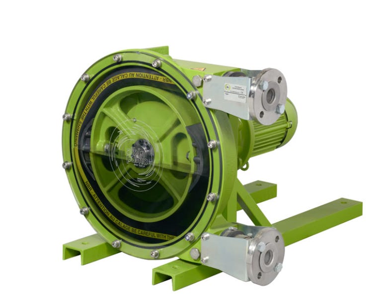
Existing designs
A peristaltic pump forces the liquid or gas through it by deforming a diaphragm or flexible tube, and thereby creating a displaced volume. The main advantage of this approach is that there are no leaks if the materials hold up.
There are 3D-printable peristaltic pumps, however these require non 3D-printed surgical tubing, as well as assembly that would be difficult to automate.
https://www.thingiverse.com/thing:1696019
Current design and design feature overview.
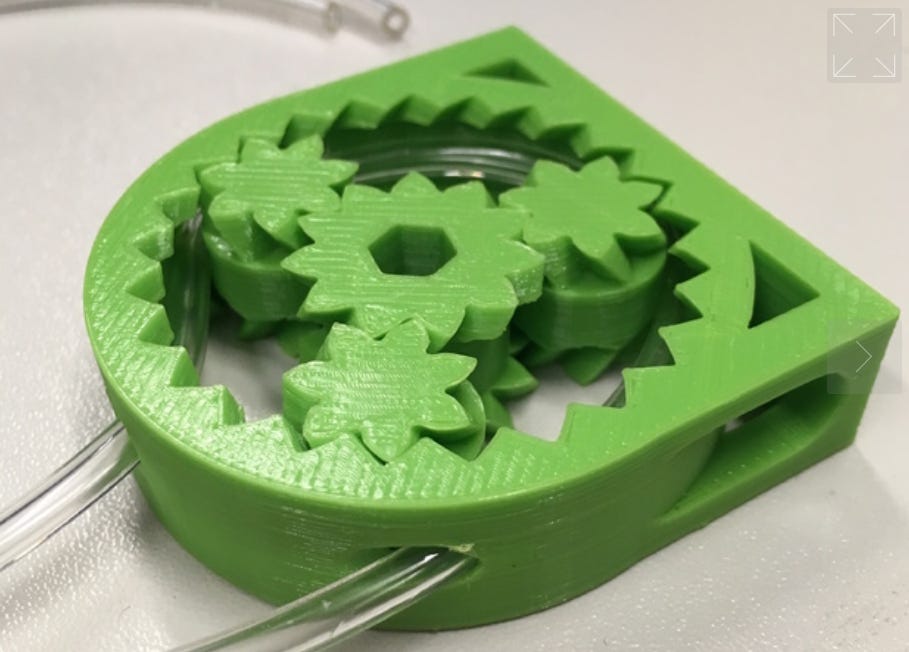
The newest design (09.01.23) is intended to be used as a development platform, the diaphragm is removable and replaceable with new designs, this allows for faster iterations of the diaphragm design (however, the diaphragm is still printable already assembled in the pump frame):
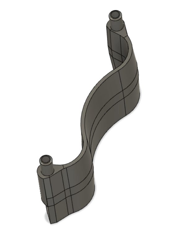
The diaphragm is completely disconnected from the “frame” of the pump, this has shown to be necessary to avoid additional stresses on the diaphragm.
All the “high stress” areas of the diaphragm body are rounded, this to avoid the slicer of creating a layer start/stop in the middle of the working area, this is important to keep the diaphragm water tight under operation, and to extend the durability. This has been discovered during testing.
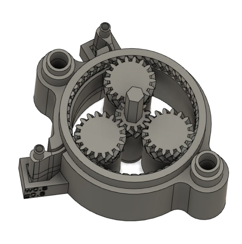
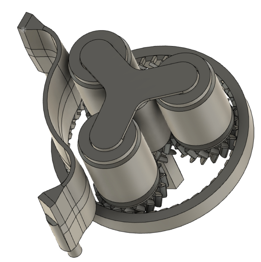
The rollers are both driven and held in place with the planetary gearset, the number of teeth and module was chosen so that the pitch circle diameter would be equal to the Theoretical rolling diameter of the rollers (rolling diameter before clearances for printing were subtracted/added). One of the big advantages of 3D-printing is that one can choose non-standard modules to achieve this with no additional cost or hassle.
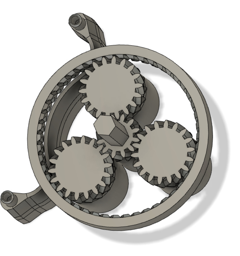
Earlier designs had a gear-set on both sides of the diaphragm, this would stop the rollers from tipping, however, it was shown that one could avoid the tipping by printing a separate planetary carrier. By doing this, design iteration time could be reduced considerably. Once the diaphragm is finalized a fully print in place version can be designed:
Diaphragm Design:
The general concept is to print a diaphragm with the same material as the rest of the pump. This presents the challenge of PLA being a relatively hard and un-elastic plastic compared to other available FDM-plastics.
In the first initial test a simple thin walled (single perimeter line - 0.4mm) dome was modelled. This showed some promise when actuating it by hand, but the layer adhesion in the diaphragm failed and started leaking when integrated into a rigid frame..
Different strategies were attempted to mitigate this issue.
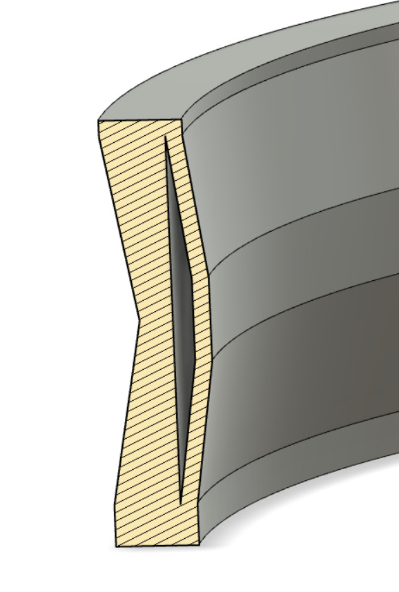
Initially the diaphragm was only a single layer line, modelled to be 0.4mm wide.
This was extended to 0.8, however this greatly reduced the overall flexibility of the structure, and induced cracking when the diaphragm was forced to do the movements that were required to pump a liquid.
It was later discovered that with cura 5.0 one could model the diaphragm witch to be as thick as 0.6mm and the slicer would still just use a single layer line to print it.
This resulted in similar flexibility as when modelled with a 0.4mm diaphragm, while subjectively making it more durable.
Continued work
Research on this part regarding durability and performance is still in the works. While it has been shown to be a challenge to achieve all the goals of this design, there is promise in the early prototypes!
The main focus going forward is going to be to achieve around 50cm of head pressure (the required amount to pump liquid up and over the printer gantry), and to make the pump as durable as possible.